Random Limits
Limits can be used to safely run a test, aborting a test if any of these limits are exceeded.
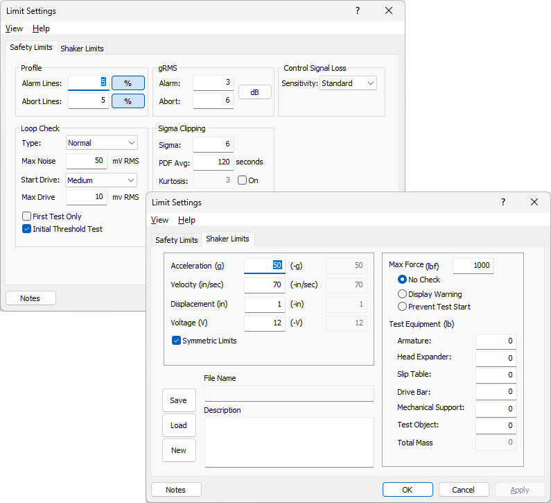
Profile
- Alarm Lines - Enter a number from 1 to the resolution, or a percent from 1 to 100. This parameter is the number of lines allowed out of tolerance before an alarm is activated.
- Abort Lines - Enter a number from 1 to the resolution, or a percent from 1 to 100. This parameter is the number of lines allowed out of tolerance before an abort is activated.
gRMS
Db units are automatically scaled if the Reference Spectrum is changed.
- Alarm - Displays a message if the control spectrum level exceeds threshold level.
- Abort - Automatically shuts down test if control spectrum level exceeds threshold. Range is from 3 to 20.
Control Signal Loss
- Standard - Measure the ambient noise (in RMS volts) on each control channel with the drive off. Increase the drive until all control channels exceed the measured ambient noise by 6dB. Measure the RMS of each control channel at the current drive level and store the RMS level. If, at any time during a test, any one of the control channel's RMS values goes more than 3dB below the above stored RMS level, the test is aborted. This method provides the safest control signal loss detection mode and will usually detect cases where an accelerometer has fallen off a test specimen, but remains on the test fixture (bouncing about).
- Low - Measure the ambient noise on each control channel (with drive off) and sets the control signal loss threshold to 3dB above this level. If, at any time during a test, any one of the control channel's RMS values goes below the above stored RMS level, the test is aborted. This method is good for large structures that may have large differences in the gains of the control channels. This method should only be used during attended tests.
- Off - Disable the control signal loss after the loop check. This method should only be used in manual mode and when the test is attended. It may be useful in noisy environments for cases where control signal loss aborts have occurred and the equipment is known to be working properly.
Loop Check
- Type - Used to select whether the loop check is normal or a more rigorous test. Also allows selecting the type of averaging to use (Linearor Exponential).
- Max Noise - Maximum acceptable ambient noise level (in mV RMS). Enter the ambient noise signal level used to decide if an input channel is too noisy to allow a test to run. This must be in the range 0-1000 mV.
- Max Drive - Maximum output level during loop check. For maximum drive (mV RMS), enter the maximum drive voltage for system output during loop check threshold search. The drive will not exceed this value if an open loop condition occurs. Higher drive levels may be necessary for noise environments or if gain is low.
- First Test Only - Check this box to run loop check on the first test only. Loop check will not be run on subsequent tests.
- Initial Threshold Test - Check this box to validate the initial level, i.e. see if it’s too low.
Sigma Clipping
- Clipping - Drive clipping allows clipping of high peaks in the output signal to prevent power amplifier overloads. However, clipping can cause a reduction in the system dynamic range. Range is from 2 to 20. A value of 20 turns off Sigma Clipping.
- Kurtosis - An indicator of the degree of variability of the random time history. A standard value of about 3 is typical for control. Higher values lead to higher time domain excursions. Range is from 3 to 20.
![]()
![]()
![]()