Panther System: Superior Capabilities for Aerospace Research & Development
Executive Summary
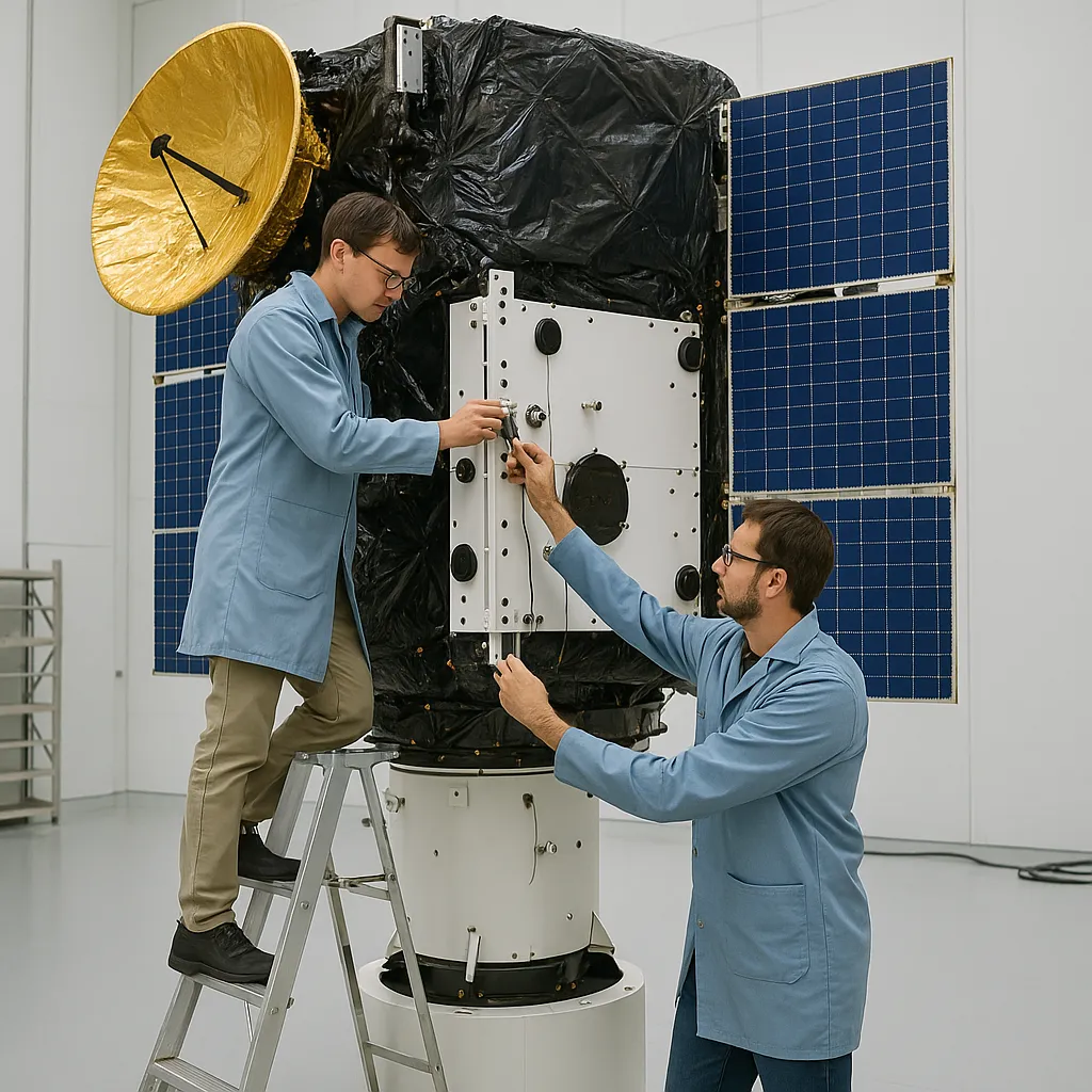
The Panther vibration control and analysis system represents the pinnacle of modern vibration testing technology, specifically engineered to meet the demanding requirements of aerospace research and development. Built on Spectral Dynamics' eight decades of vibration instrumentation expertise and heritage as the inventor of closed-loop digital vibration control, Panther delivers unparalleled measurement accuracy, data integrity, and analytical capabilities critical for aerospace applications.
This technical paper demonstrates how Panther's advanced features—including Process Lines for adaptive monitoring, direct stream-to-disk architecture, superior dynamic range and accuracy specifications, proprietary Composite Plot visualization, and specialized 100 kHz tachometer hardware—provide aerospace engineers with the tools necessary to conduct rigorous R&D testing that meets or exceeds industry standards.
1. Introduction: Aerospace R&D Testing Requirements
Aerospace research and development demands vibration control systems capable of:
- Precise, repeatable measurements with exceptional accuracy
- Complete data capture without loss or gaps during critical transient events
- Real-time adaptive monitoring and alarm capabilities
- High-resolution frequency and time-domain analysis
- Comprehensive visualization tools for rapid diagnostic assessment
- Validation of rotating machinery and structural dynamics
The Panther system addresses each of these requirements through purpose-built hardware and software capabilities that distinguish it from conventional vibration control systems.
2. Process Lines: Adaptive Monitoring for Critical Parameters
2.1 Overview and Aerospace Applications
Process Lines represent one of Panther's most powerful features for aerospace R&D testing. This sophisticated monitoring system enables engineers to define custom analytical calculations that execute in real-time during data acquisition, providing immediate feedback on critical system parameters.
In aerospace applications, Process Lines enable:
- Real-time resonance tracking during frequency sweeps or run-up/coast-down testing
- Adaptive alarm thresholds based on operating conditions (speed, temperature, load)
- Continuous monitoring of critical frequencies associated with structural modes
- Order tracking for rotating machinery components (turbines, gearboxes, propulsion systems)
- Automated detection of anomalous vibration patterns indicating potential failure modes
- Band-pass monitoring of specific frequency ranges of interest
2.2 Technical Implementation
Process Lines utilize sophisticated digital signal processing to extract specific information from the acquired data stream. Engineers can define multiple process types:
- Mode Lines: Track specific resonant frequencies with user-defined bandwidth
- Order Tracking: Monitor harmonics of fundamental rotational frequency
- Band-Pass Processing: Analyze energy within specified frequency ranges
- Residual Analysis: Identify vibration components not explained by defined orders or modes
Each Process Line can be configured with independent alarm thresholds, enabling automated test abort conditions when critical parameters exceed acceptable limits. This capability is essential for protecting expensive aerospace test articles while gathering maximum data during controlled testing.
Example Application: During turbine engine testing, Process Lines can simultaneously monitor multiple blade passing frequencies, track shaft orders, and detect bearing defect frequencies—all while streaming complete waveform data to disk for post-analysis. This multi-parameter approach provides immediate test feedback while preserving all data for detailed forensic analysis.
3. Stream-to-Disk Architecture: Complete Data Integrity
3.1 Gap-Free Acquisition
Panther implements a sophisticated gap-free, real-time streaming architecture that writes all acquired data directly to the host PC disk in all applications. This fundamental capability ensures that no transient events, impulses, or critical data are lost during testing—a requirement that cannot be compromised in aerospace R&D environments.
Key advantages for aerospace testing:
- Complete capture of transient events (flutter onset, resonance crossings, impact responses)
- Unlimited test duration without data loss or buffer overflow
- Direct streaming eliminates memory constraints that plague competing systems
- Immediate availability of complete time histories for post-analysis
- Enables correlation between multiple test parameters over extended durations
- Supports forensic analysis of unexpected test events or failures
3.2 Multiple Independent Data Streams
Panther's exclusive capability to define multiple data streams, each with independent sample rates, represents a significant advantage for complex aerospace testing. This feature allows simultaneous acquisition of:
- High-frequency structural response data (100+ kHz) for acoustic measurements
- Medium-frequency vibration data (20-50 kHz) for standard transducers
- Low-frequency rotational dynamics (1-10 kHz) for speed and load monitoring
- Ultra-low-frequency thermal or strain measurements (1-100 Hz)
The highest bandwidth stream can write to disk simultaneously without compromise to sampling rate or data integrity. This eliminates the need to choose between high-frequency capture and efficient data storage—aerospace engineers can have both. Aerospace engineers can then optionally post process the high speed stream using the software’s internal filter/decimation options to analyze sub bandwidths, a capability no other vibration control system provides.
4. Superior Dynamic Range and Measurement Accuracy
4.1 24-Bit ADC Resolution and >110 dB Dynamic Range
The Panther input subsystem utilizes 24-bit analog-to-digital converters (ADCs) on all channels, achieving dynamic range exceeding 110 dB. This exceptional specification provides aerospace engineers with the measurement capability required for testing scenarios involving:
- Wide amplitude variations during resonance sweeps
- Simultaneous measurement of small vibrations and large structural responses
- Low-level signature analysis in the presence of dominant operating frequencies
- Detection of incipient bearing failures while monitoring overall machine vibration
- Measurement of noise floor characteristics during acoustic testing
The practical significance: With >110 dB dynamic range, Panther can resolve signals that differ in amplitude by more than 300,000:1. This allows measurement of a 0.01g background vibration while simultaneously monitoring a 30g resonance response without range-switching or multiple acquisition passes.
4.2 Industry-Leading Amplitude Accuracy
Panther specifications for amplitude accuracy are:
±0.20% of value OR ±0.03% of full scale, whichever is greater
This specification applies to both amplitude accuracy and amplitude linearity, ensuring that measurements maintain precision across the entire measurement range. For aerospace qualification testing where specification limits may be tight, this accuracy level provides confidence that measured values represent true physical response.
Additional accuracy features:
- Channel-to-channel amplitude matching better than ±0.25 dB
- Phase accuracy better than ±1.0 degrees to 100 kHz (single unit)
- Frequency accuracy of ±5 ppm (parts per million)
- Internal digital calibration referenced to NIST standards
- Automatic temperature compensation and drift correction
4.3 Comparison to Competitive Systems
Many competing vibration control systems claim theoretical dynamic ranges based on ADC bit depth (e.g., 144 dB from 24-bit converters) without accounting for real-world limitations such as:
• Analog noise floor from signal conditioning
• Quantization noise in practical operating conditions
• Thermal drift and electromagnetic interference
• Anti-aliasing filter noise contributions
• Ground loop and common-mode rejection limitations
Spectral Dynamics' specification of >110 dB dynamic range represents achievable, real-world performance rather than theoretical maximums. This honest engineering approach ensures that aerospace engineers can rely on specified performance in actual test environments.
5. Proprietary Composite Plot: Advanced Diagnostic Visualization
5.1 Introduction to Composite Plot
The Composite Plot is a unique, proprietary visualization tool exclusive to Spectral Dynamics systems. This sophisticated display combines multiple correlated parameters into a single three-dimensional representation, providing aerospace engineers with unprecedented insight into complex vibration phenomena.
The Composite Plot simultaneously presents:
- Frequency spectrum vs. time or rotational speed (waterfall/Campbell diagram)
- Time-domain waveform visualization
- Rotational speed or record number tracking
- Frequency-domain peak cursors with automatic tracking
- Min/max amplitude history across the test duration
- Order tracking overlay for rotating machinery
5.2 Aerospace Applications
Turbine Engine Testing:
During run-up and coast-down testing, the Composite Plot enables immediate visualization of:
- Blade pass frequencies and their harmonics as functions of speed
- Critical speed crossings and resonance amplitudes
- Order tracking behavior through the operating envelope
- Bearing defect frequencies and their evolution with speed
- Structural mode shapes excited at specific operating conditions
Structural Dynamics Testing:
The Composite Plot reveals:
- Modal frequency shifts due to thermal effects or loading
- Damping ratio variations across test conditions
- Coupling between structural modes
- Non-linear stiffness behavior at high amplitudes
- Frequency response evolution during sine sweeps
5.3 Diagnostic Efficiency
The Composite Plot significantly reduces diagnostic time by presenting complex multi-dimensional data in an intuitive, immediately interpretable format. Where conventional systems might require exporting data, loading into separate analysis software, and generating multiple plots, Panther's Composite Plot provides instant visualization during or immediately after testing.
This capability is particularly valuable in aerospace R&D environments where:
- Test time on expensive facilities is limited
- Rapid iteration of test conditions is necessary
- Immediate feedback determines subsequent test modifications
- Multiple stakeholders need to understand results quickly
- Documentation must be generated efficiently for program reviews
6. Specialized 100 kHz Tachometer Hardware
6.1 High-Speed Tachometer Capabilities
Panther includes dedicated hardware tachometer input capable of 100 kHz frequency resolution providing precision speed measurement and critical for rotating machinery analysis in aerospace applications. Specifically, the tachometer hardware utilizes a 100 MHz clock with double-buffered counter architecture, enabling extremely accurate frequency measurements.
6.2 Technical Architecture
The tachometer subsystem employs:
- 100 MHz reference clock for high-resolution time measurement
- Double-buffered counters to prevent missing or combining tachometer cycles
- Decoupled timing from data acquisition sample rate
- Continuous counter operation to avoid skipping triggered cycles
- Configurable averaging for very high input frequencies
- Support for fractional pulses-per-revolution for intermediate shaft tracking
6.3 Accuracy and Resolution
With a 100 MHz clock, the tachometer achieves count resolution of 10 nanoseconds. The internal specification for counting accuracy is 1 count in 1000, meaning the count value should be at least 1000 to ensure accurate results. At this minimum count value, the system accurately measures tachometer frequencies up to 100 kHz (6 million RPM equivalent).
Practical applications:
- Turbine blade passing frequencies: With 50 blades at 20,000 RPM fundamental, blade passing frequency is approximately 16.7 kHz—well within tachometer capability
- Gear mesh frequencies: 100-tooth gear at 10,000 RPM produces mesh frequency of approximately 16.7 kHz
- High-speed bearing analysis: Inner race defect frequencies of high-speed bearings requiring precise tracking
6.4 Integration with RMA and Composite Plot
The 100 kHz tachometer hardware integrates seamlessly with Panther's Rotating Machinery Analysis (RMA) application and Composite Plot visualization. This integration enables:
- Digital Tracking sampling: Sample rate continuously adjusted to maintain constant samples-per-revolution regardless of speed variations
- Order domain analysis: Transform time-domain data into order domain for machine diagnostic analysis
- Phase-referenced measurements: Establish consistent phase relationship for vibration signature analysis
- Campbell diagram generation: Automatic creation of frequency vs. speed plots showing critical speed crossings
The combination of hardware tachometer precision, Process Line monitoring, and Composite Plot visualization provides a comprehensive rotating machinery diagnostic capability unmatched in the industry.
7. GTX Software Environment and System Integration
7.1 Unified Testing Platform
All Panther capabilities—vibration control, RMA, transient analysis, and spectral processing—operate within the unified GTX software environment. This integration provides:
- Consistent user interface across all applications
- Panther Library for organized access to test setups and data
- Seamless transitions between control, acquisition, and analysis modes
- Touch-screen compatible operation for modern tablets and surfaces
- Comprehensive safety monitoring (>12 parameters checked 25× per second)
- Automated report generation with customizable templates
7.2 Safety and Reliability
Aerospace testing often involves expensive test articles and high-energy excitation. Panther's integrated safety system continuously monitors critical parameters including:
- Channel overload detection (analog and digital)
- Abort line violations (tolerance limits) with Process Lines
- Hardware communication integrity
- Thermal conditions
Automatic abort sequences protect both equipment and test articles while preserving all data up to the abort event for forensic analysis. Process Lines capability can be defined over specific rpm or other defined Gate parameter for monitoring/logging and checking Alarm and Abort tolerance specifications.
8. Real-World Aerospace R&D Challenges: Panther Solutions
The following examples demonstrate how Panther's advanced capabilities directly address critical measurement challenges encountered in aerospace research and development environments. Each case study illustrates specific technical problems and explains how Panther's unique features provide superior solutions.
8.1 Turbine Engine Blade Resonance and High Cycle Fatigue
The Challenge:
Turbine blades in jet engines operate under extreme conditions with temperatures exceeding 1,500°C and rotational speeds up to 20,000 RPM. High cycle fatigue (HCF) caused by resonant vibration is a leading cause of turbine blade failure. When a blade's natural frequency coincides with an excitation frequency (such as blade passing frequency, vortex shedding, or combustion dynamics), resonance amplifies vibration amplitude dramatically, leading to crack initiation and propagation.
The critical measurement challenge is identifying resonant frequencies during run-up and coast-down testing across the full operating envelope (idle to maximum power) while simultaneously tracking:
- Blade passing frequencies (BPF) and harmonics—with 50-100 blades at 15,000-20,000 RPM, BPF can reach 15-30 kHz
- Structural modes of individual blades (typically 2-8 kHz for first modes)
- Engine order components (1X, 2X, 3X shaft speed)
- Critical speed crossings where operating frequencies intersect structural resonances
- Phase relationships between multiple measurement points
Traditional systems struggle with: Limited dynamic range forces compromise between measuring low-amplitude background vibration and high-amplitude resonance peaks; inadequate frequency resolution at high speeds; inability to capture complete transient data during rapid accelerations; and difficulty correlating speed-dependent phenomena across multiple channels.
The Panther Solution:
Process Lines with Speed-Dependent Tracking: Panther's Process Lines can be configured to track specific blade modes as functions of rotational speed. Engineers define Mode Lines that automatically follow resonant frequencies as they shift with temperature and centrifugal stiffening effects. Real-time alarm thresholds detect when vibration amplitude exceeds acceptable levels at critical speeds, enabling immediate test abort before blade damage occurs.
>110 dB Dynamic Range: The exceptional dynamic range allows simultaneous measurement of 0.1g background vibration and 50g+ resonance peaks without range switching or saturation. This is critical during frequency sweeps where vibration amplitude can change by three orders of magnitude within seconds.
100 kHz Tachometer with Order Tracking: The hardware tachometer provides precise speed measurement even during rapid acceleration (>1,000 RPM/sec). Order tracking transforms time-domain data into the order domain, making it trivial to identify which engine orders (1X, 2X, blade passing frequencies) are exciting structural modes. The Composite Plot displays this information as a Campbell diagram, instantly revealing critical speed crossings.
Gap-Free Streaming: Complete capture of the entire run-up/coast-down transient (often 5-15 minutes) ensures that no critical events are missed. Post-analysis can examine any portion of the test in detail, including extracting precise frequency and damping estimates at specific speed points.
Result: Aerospace engineers can confidently identify all resonant conditions across the operating envelope, validate finite element models against test data, and establish safe operating margins—all while protecting expensive turbine hardware from destructive vibration.
8.2 Wing Flutter Detection and Aeroelastic Stability
The Challenge:
Flutter is a catastrophic self-excited aeroelastic instability that has destroyed numerous aircraft. It occurs when aerodynamic forces couple with structural dynamics, creating positive feedback that amplifies vibration exponentially. Flutter can manifest in multiple forms:
- Classical wing flutter: coupling of wing bending and torsional modes (typically 2-15 Hz)
- Control surface flutter: aileron, elevator, or rudder oscillation (5-50 Hz)
- Transonic dip: sudden reduction in flutter speed near Mach 1.0 due to shock wave effects
- Panel flutter: high-frequency skin vibration in supersonic flow (100-500 Hz)
Ground vibration testing (GVT) precedes flight flutter testing to validate finite element models and identify coupled modes. The measurement challenge is detecting subtle changes in modal frequency and damping that indicate proximity to flutter onset. Engineers must measure:
- Multiple structural modes simultaneously (wing bending, torsion, fuselage, empennage)
- Precise damping ratios (typically 0.5-5% of critical) to track stability margins
- Mode shape correlation across 100+ measurement points
- Frequency response functions with high resolution (<0.01 Hz) at low frequencies
- Transient response to excitation (impulse, step, or swept sine)
Traditional challenges: Insufficient channel count requires multiple test runs with sensor repositioning; limited frequency resolution prevents accurate damping estimation; inability to distinguish closely spaced modes; phase measurement errors compromise mode shape identification.
The Panther Solution:
- 32-Channel Expandability with Phase Accuracy: Panther supports up to 32 fully phase-synchronized channels, enabling comprehensive spatial coverage in a single test. The ±1.0° phase accuracy to 100 kHz ensures accurate mode shape determination, critical for correlating test data with analytical models.
- High-Resolution Spectral Analysis: With FFT frame sizes up to 16,384 points (and up to 524288 in 64 bit versions) and variable bandwidth settings, Panther achieves frequency resolution better than 0.005 Hz at low frequencies. This resolution is essential for separating closely spaced modes and accurately estimating damping from half-power bandwidth measurements.
- Process Lines for Modal Tracking: Engineers define Mode Lines at expected structural frequencies. As excitation frequency sweeps through the range, Process Lines track peak amplitude and bandwidth, automatically identifying resonances and calculating damping ratios in real-time. Alarm thresholds detect dangerously low damping values.
- Multiple Data Streams: Low-frequency structural modes (2-15 Hz for wing flutter) can be sampled at 256 Hz while simultaneously capturing high-frequency panel vibration (100-500 Hz) at 5 kHz sample rate. This eliminates the need for separate test runs and ensures correlation between different frequency regimes.
- Composite Plot Visualization: The proprietary Composite Plot displays frequency response across all channels simultaneously, with waterfall format showing evolution over time or excitation frequency. Engineers instantly identify coupled modes, track frequency shifts due to structural loading or temperature, and validate that mode shapes match predictions.
Result: Complete ground vibration characterization in a single test session, with confidence that all critical modes have been identified and that the aircraft structure has sufficient stability margins before proceeding to flight flutter testing.
8.3 Early Detection of Rolling Element Bearing Defects
The Challenge:
Rolling element bearings in aerospace applications (turbine engines, gearboxes, actuators, control systems) must operate with extreme reliability. Bearing failure can lead to catastrophic consequences including engine seizure, loss of control, or structural damage. Early defect detection is critical but technically challenging.
Bearing defects generate characteristic vibration signatures based on geometry and rotational speed:
- Ball Pass Frequency Outer Race (BPFO): typically 3-7× shaft speed
- Ball Pass Frequency Inner Race (BPFI): typically 4-9× shaft speed
- Ball Spin Frequency (BSF): typically 2-4× shaft speed
- Fundamental Train Frequency (FTF): typically 0.3-0.5× shaft speed (cage rotation)
Early-stage defects produce low-amplitude, impulsive signals that are easily masked by other machinery vibration. The diagnostic signature consists of:
- High-frequency resonance excitation (10-40 kHz) from impulsive contact
- Modulation sidebands around bearing frequencies
- Amplitude variations as defects enter/exit load zones
- Progression from discrete frequencies to broadband noise as damage worsens
Measurement difficulties: Bearing defect frequencies are typically 10-100× smaller in amplitude than dominant machine vibration (gear mesh, blade passing, imbalance); high-frequency components require wide bandwidth and high sample rates; speed variations cause frequency modulation; multiple bearing frequencies can overlap.
The Panther Solution:
- >110 dB Dynamic Range for Low-Level Detection: Panther's exceptional dynamic range enables detection of bearing defect signals that are 60-80 dB below the dominant vibration sources. A 0.01g bearing defect signature can be resolved even when overall machine vibration is 10g+.
- High Sample Rate with Multiple Streams: One data stream samples at 262 kHz to capture high-frequency bearing resonances (envelope analysis frequency range: 10-100 kHz), while a second stream at 20 kHz captures lower-frequency machine vibration. This dual-stream approach optimizes both detection sensitivity and data storage efficiency.
- Order Tracking with 100 kHz Tachometer: The hardware tachometer enables order tracking that transforms speed-dependent bearing frequencies into stationary order components. BPFO, BPFI, BSF, and FTF appear as discrete orders regardless of speed fluctuations, dramatically improving detection SNR and enabling coherent averaging.
- Process Lines for Automated Monitoring: Engineers configure Process Lines to track calculated bearing frequencies (based on geometry and measured speed). Real-time amplitude monitoring provides immediate alarm when bearing defect energy exceeds thresholds. Process Lines can track multiple bearings simultaneously, each with its own geometry and defect frequencies.
- Composite Plot for Trend Analysis: The Composite Plot displays bearing defect frequency evolution over time or operating conditions. Engineers observe the characteristic progression from single-frequency components (early defect) to harmonic families with sidebands (developing defect) to broadband noise floor (advanced damage). This enables accurate remaining useful life estimation.
- Gap-Free Data for Envelope Analysis: Complete time-history capture enables sophisticated post-processing including envelope analysis, spectral kurtosis, and cepstrum analysis—advanced techniques that extract weak bearing signals from strong interference. All data is available for forensic analysis if unexpected failures occur.
Result: Detection of bearing defects 10-100 hours before conventional methods, enabling planned maintenance and preventing catastrophic failures. This capability is especially critical for aerospace applications where in-flight bearing failure could be life-threatening.
8.4 Dual-Rotor Turbine Engine Dynamic Coupling Analysis
The Challenge:
Modern turbofan engines employ dual-rotor (or triple-rotor) configurations with concentric shafts rotating at different speeds. The high-pressure (HP) rotor typically operates at 10,000-20,000 RPM while the low-pressure (LP) rotor operates at 3,000-8,000 RPM. These rotors are aerodynamically coupled, meaning their vibration characteristics interact in complex ways.
Critical measurement challenges include:
- Vibration transmission through squeeze-film dampers and inter-shaft bearings
- Coupled rotor-casing modes where both rotors and stationary structure vibrate together
- Sum and difference frequency interactions (HP ± LP speeds)
- Critical speed crossings for both rotors within operating envelope
- Subsynchronous vibrations that don't correspond to either rotor speed
- Accessory gearbox vibration transmitted to main engine structure
Test engineers must simultaneously track vibration at multiple locations (fan case, HP compressor, HP turbine, LP turbine, bearing housings) while correlating with both rotor speeds. Traditional single-tachometer systems cannot adequately characterize dual-rotor dynamics.
The Panther Solution:
- Multi-Tachometer Order Tracking: Panther's RMA application supports multiple tachometer inputs (HP and LP rotors), each with independent order tracking. The system calculates orders relative to each rotor independently, plus sum and difference frequencies. This reveals coupling mechanisms invisible to single-rotor analysis.
- Process Lines for Multi-Rotor Monitoring: Engineers define Process Lines that track HP rotor orders (1×HP, 2×HP, blade passing frequencies), LP rotor orders (1×LP, 2×LP, fan blade passing), and interaction terms (HP+LP, HP-LP, 2HP-LP, etc.). Real-time monitoring identifies unexpected coupling phenomena during development testing.
- 32-Channel Spatial Coverage: Simultaneous measurement at fan case, compressor cases, turbine frames, and bearing housings provides complete spatial picture of vibration propagation. Phase measurements between channels identify vibration transmission paths and structural mode shapes.
- Composite Plot with Dual-Rotor Campbell Diagrams: The Composite Plot displays frequency versus both HP and LP rotor speeds in three-dimensional format, revealing critical speed crossings and coupled modes that would be invisible in conventional 2D plots. Engineers instantly identify where HP rotor natural frequencies intersect LP blade passing frequencies, or vice versa.
- Gap-Free Capture of Transient Events: Complete data streaming captures entire start-up sequences where both rotors accelerate through multiple critical speeds in complex patterns. Post-analysis examines any transient response in detail, including decay rates that indicate structural damping and stability.
Result: Comprehensive characterization of dual-rotor dynamics, validation of analytical models including gyroscopic effects and bearing stiffness, and identification of potential resonance conditions before flight certification testing. This capability is essential for modern high-bypass turbofan development.
9. Conclusion: The Panther Advantage in Aerospace R&D
The Panther vibration control and analysis system delivers measurable advantages for aerospace research and development through:
- Process Lines enabling real-time adaptive monitoring and intelligent alarming
- Gap-free stream-to-disk architecture ensuring complete data integrity
- Multiple independent data streams optimizing bandwidth and storage efficiency
- Superior >110 dB dynamic range and ±0.20% accuracy for precise measurements
- Proprietary Composite Plot for rapid diagnostic visualization
- Specialized 1 MHz tachometer hardware for precision rotating machinery analysis
- Comprehensive integration within the GTX software environment
These capabilities combine to create a vibration testing platform specifically engineered for the demanding requirements of aerospace applications—where measurement accuracy, data completeness, and diagnostic efficiency directly impact program success.
Spectral Dynamics' commitment to honest engineering specifications, combined with eight decades of vibration instrumentation expertise, ensures that Panther delivers real-world performance that aerospace engineers can depend on for critical R&D testing.