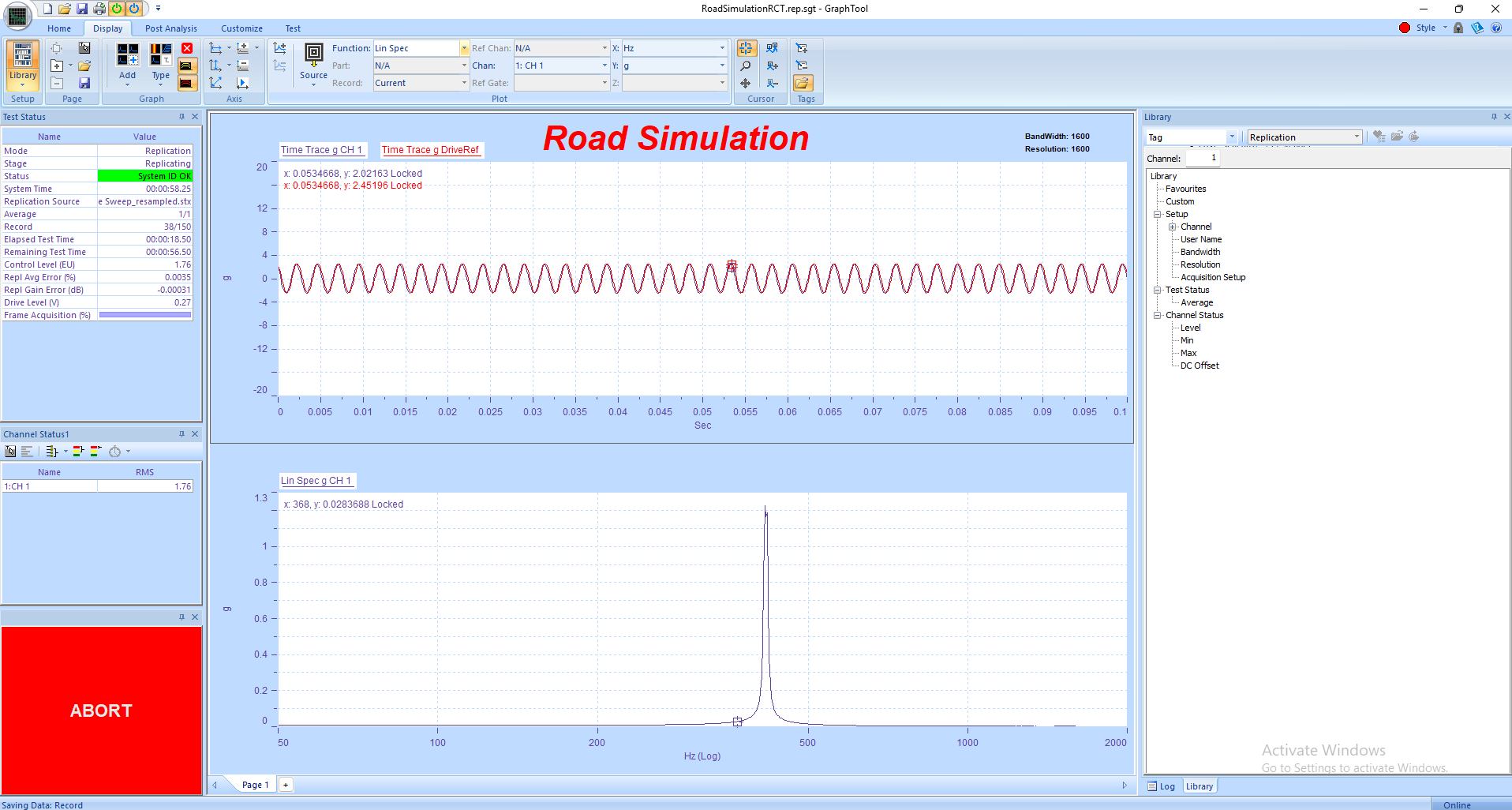
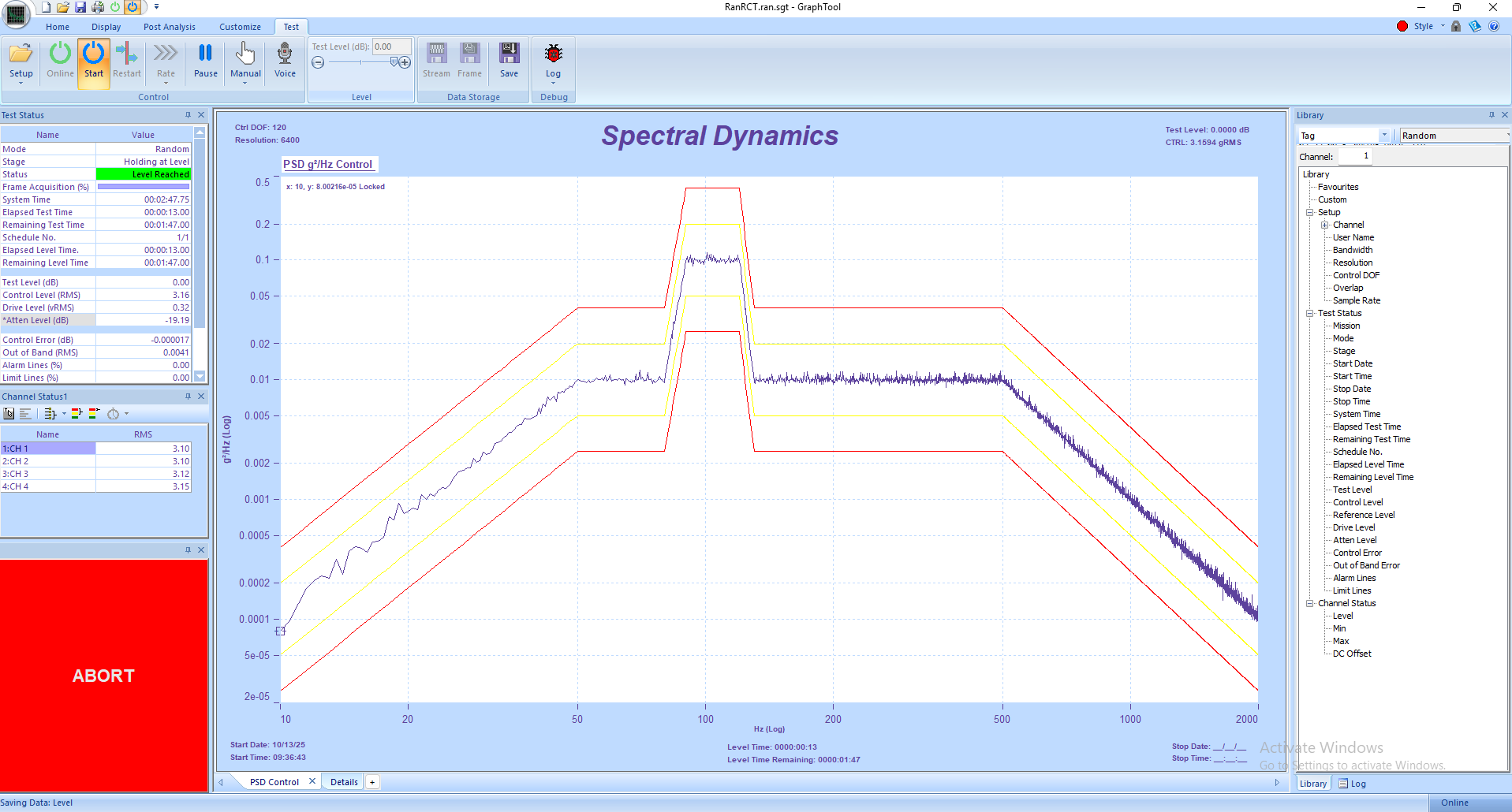
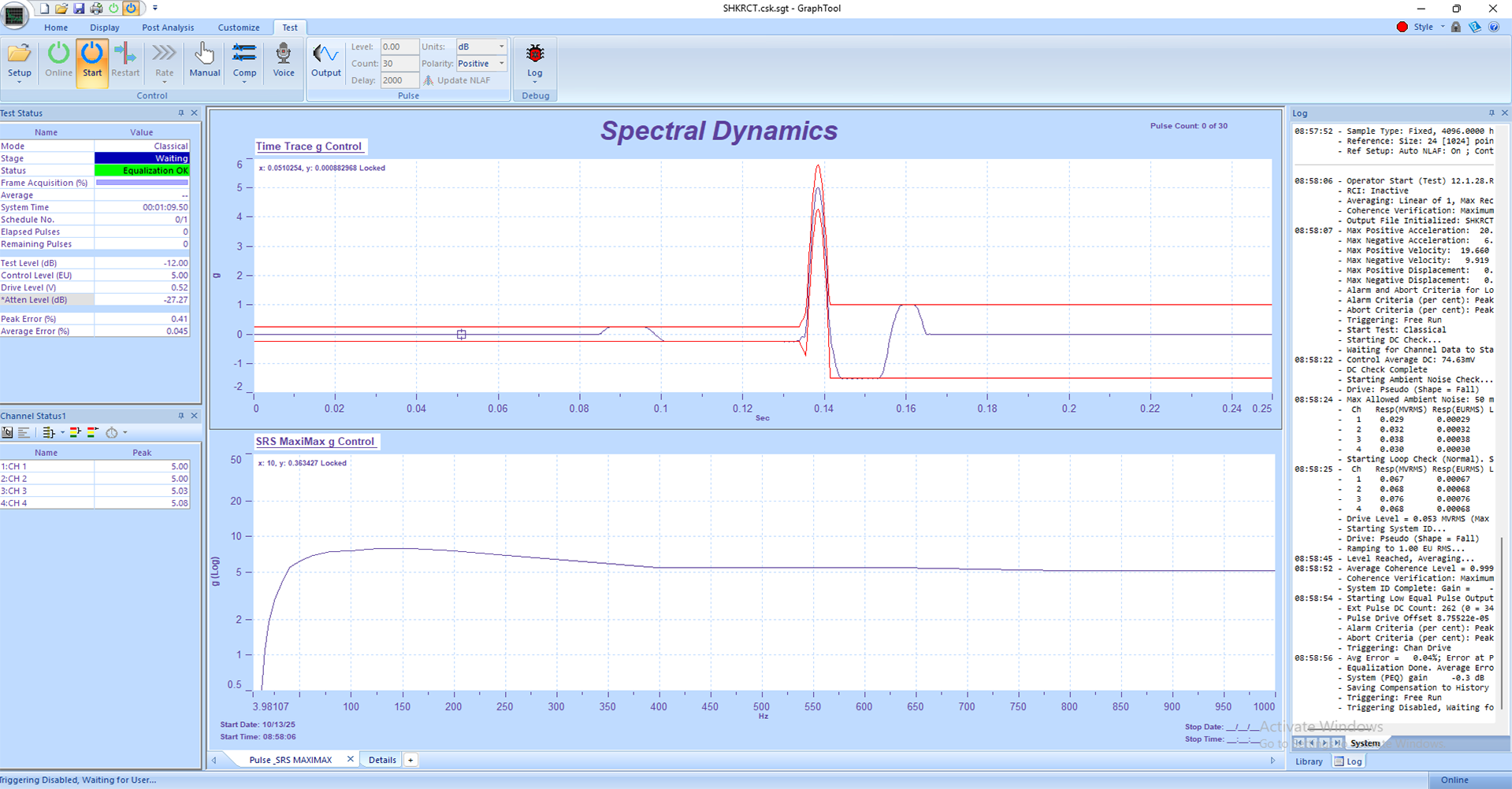
Stepped Sine Vibration Tutorial
How to Run a Basic Stepped Sine Vibration Test on the Panther Control System
1. Safety First
• Stepped Sine testing applies discrete frequency tones one at a time to identify system response — ensure all personnel are clear of the test area before beginning.
• Inspect all shaker, amplifier, and sensor connections before powering up. Verify that mechanical fixturing is tight and secure.
• Confirm the shaker and amplifier are rated for the full range of test frequencies and amplitudes to be applied.
• Verify accelerometer orientation and grounding, and confirm TEDS identification for all sensors before the test begins.
• Ensure Abort, Stop, and Emergency Power Off (EPO) buttons are within reach and tested prior to operation.
• Panther’s built-in safety system monitors more than a dozen critical parameters up to 25 times per second, automatically aborting the test if unsafe conditions occur to protect the test article, shaker, and personnel.
2. System Setup
1. Power on the Panther control hardware and the amplifier, keeping the amplifier in standby until setup verification is complete.
2. Launch the Panther Stepped Sine control application on the host PC.
3. If not already connected to the hardware, navigate via the Setup→ Set Input Type menu in the Panther software to establish hardware connection.
4. Verify that all input channels are active, calibrated, and functioning correctly. Panther’s internal NIST-referenced digital calibration ensures accuracy.
5. Select the output channel that drives the shaker amplifier input and verify signal polarity.
6. Use the Library to open a saved Stepped Sine setup or create a new one. Panther’s Library system provides alias-based organization for quick recall of previous tests.
3. Defining the Stepped Sine Test
1. In the Control tab, select the Stepped Sine test type.
2. Define frequency range, step size, dwell time at each frequency, and control level (in g RMS, g Peak, or displacement).
3. Assign the control and monitor accelerometer channels. Verify channel sensitivities and units for each input channel.
4. Set control tolerances, warning, and abort limits for drive and response channels. Panther’s safety system performs automatic pre-test verification before starting.
5. Enable Tracking Filters to ensure accurate measurement of amplitude and phase at each step frequency.
6. Activate Adaptive Control to maintain precise amplitude stability at each frequency step, even in the presence of test article resonances.
7. If desired, enable Multiple Acquisition Streams to record select channels at different sample rates for detailed signal capture.
8. Save the configuration before proceeding to the test run.
4. Running the Test
1. Set the amplifier to ‘Operate’ mode after verifying all setup parameters and safety conditions.
2. Press Start in the GTX toolbar to begin. Panther performs a pre-test validation sequence to ensure safe operation and proper signal routing.
3. The system applies each frequency step in sequence, holding for the defined dwell time at each step to measure control and response.
4. Monitor live amplitude, phase, and drive voltage plots in GTX. Use Status Panels to track RMS levels, warnings, and safety limits.
5. Panther’s adaptive equalization maintains precise control of amplitude across all frequency steps, ensuring accurate frequency response measurements.
6. If any limit or safety condition is violated, Panther will automatically abort the test. The operator may also use the Abort button to safely stop at any time.
5. Data Review and Reporting
• Upon completion, Panther automatically saves control, response, and drive data to the Library for easy access and traceability.
• Use GraphtoolX (GTX) to view PSD plots, phase data, and transfer functions. Overlay results from multiple runs for comparison.
• Export results directly from GTX to Word, Excel, or PDF using the Share function for reporting and documentation.
• Use Composite or Waterfall plots to visualize how response amplitude varies with frequency.
6. Panther Advantages in Stepped Sine Testing
• Safety-First Design: Monitors 12+ safety parameters 25 times per second for operator and equipment protection.
• Adaptive Equalization: Automatically adjusts drive amplitude for stable control even near resonances or non-linear regions.
• Tracking Filters: Provides precise amplitude and phase measurements at each frequency step for high-resolution transfer function data.
• Ease of Use: GTX’s modern, touch-friendly interface simplifies test setup and data review.
• High Precision: 24-bit ADCs, >110 dB dynamic range, and <1° phase match up to 100 kHz ensure superior measurement accuracy.
• Real-Time Streaming: Panther supports gap-free data recording, ensuring no loss of transient information.
• Library Integration: Allows fast recall of prior setups and results, improving testing efficiency.
7. Best Practices
• Perform a low-level test sweep before applying full test levels to verify safety and system response.
• Use the pre-test verification and abort limit setup to prevent overdrive conditions at resonances.
• Ensure accelerometers are firmly mounted at key measurement points for accurate phase and amplitude data.
• Save GTX layout templates to maintain a consistent view of key plots and parameters between tests.
• Regularly back up calibration constants and Library files to maintain data integrity and repeatability.


